Professional built Sandrail for the street!!!!!!!!
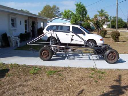
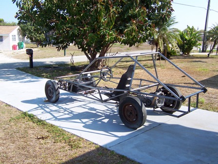
Hello and welcome to my new page and project! I started this car with the intention of achieving two goals. To build a car without having the hassle of bending tubing up and to show the home builder a way to build a buggy cheaper! Below , you will find a lot of pictures about the build and I will try to get the text for them as time goes along. The first picture is what got me started on the design and the idea of not having to use a bender. I found it on the web and used it for the basic design and modified it as needed.
Announcement: To help fund this site I am now offering Buggy plans for sale. Click on the link below to purchase and download them today!!! You wont be disappointed!

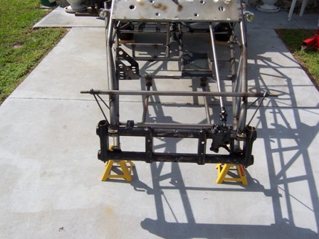
The following pictures are the early stages of the build. You can see the small changes I made to allow for the "No Bend" concept.
This is a side shot early on in the build. Basically getting all the ergonomics right and getting the tabs and brackets fitted into place for all the mounting points for later on in the build.
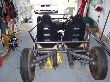
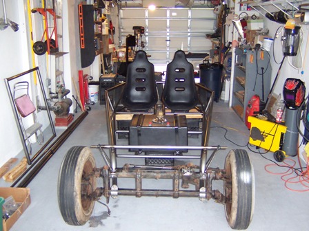
This shot shows the placement of the two seats and also shows the sides and how the joints were made without bends. The rear suspension has been sand blasted and the front openings where it was cut from the original frame have been capped and dressed up for final painting.
The bus trans front mount is done and the rear engine cradle is semi complete sans the motor mounts.
Another view of the rear section.
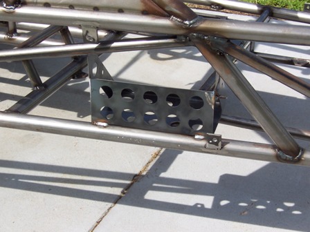
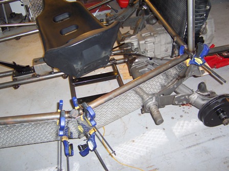
This is an aftermarket battery mount. It was designed to weld to the rear torsion housing but I decided to mount it up front for easier access and to keep it cleaner. I removed the round mounting tabs and dressed and rounded all the corners and edges and then stitch welded it in place enough to hold the weight and still have a nice clean look to it. I also welded a ground bolt, (top right side of the box) to it for the negative on the battery so it would have a nice, neat short cable.
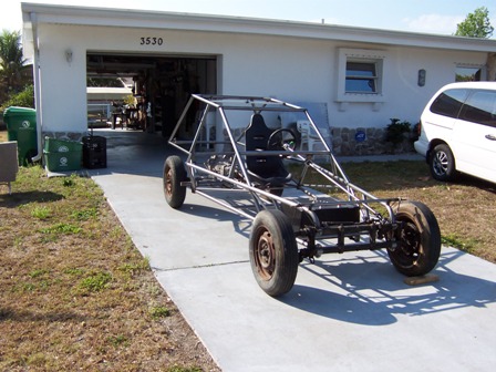
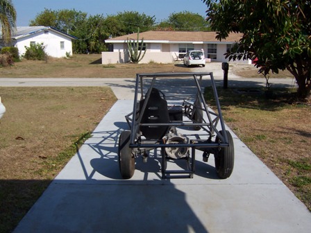
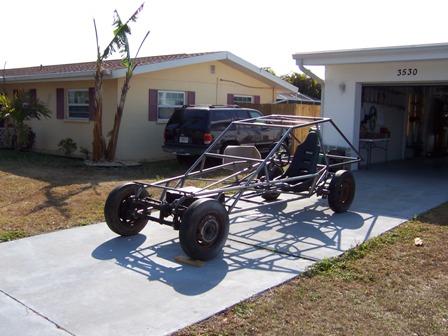
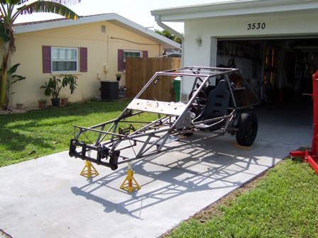
This shot and the next are general views. You cant really see it, but I set the top of the front axle beam back about 5 degrees so it would have a lot of caster in it like the old street rods and a lot of drag cars have in them. This lets the car track better at high speeds and when parked, it lets the wheels "flop" a lot when turned all the way to one side for a different look!
I bought a recondition front axle beam from J C Whitney and removed the front shock tower mounts from each side just above the top tube and then capped them with 1/8 inch x 2 inch strap. They extend forward past the stock mount 6 inches and now give me a place to mount the street legal headlights I got from Speedway. I wasn't really happy with the beam when I received it. The paint on it looked like a ten year old did it. Could not tell what kind it was and it was still very sticky an gooey. I started to clean it up only to find they had painted over the rust it had on it. I sent it out for sand blasting and then made the changes I wanted to it. I wouldn't buy another without calling them and making sure that where ever they get them from would not send another with this poor quality!
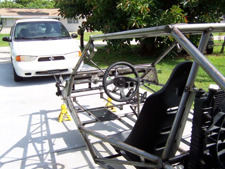
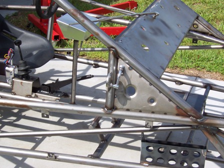
Driver side shot. You can see the steering column bracing as well as the adjustable foot pedal base plate installed in the floor that I made. Also, on the top right of the shot, you can see the end caps I used to close out the tubing. I had a local shop make up some plugs from 1.5" bar stock cut on a band saw. These are 1/8" thick so they could be welded and dressed out easily without the welder burning through them. Right center of the shot, you can see the upper radiator mount and seat belt mount,( below ). This was the only practical place to set the radiator so it would get the proper air flow. If it was placed in front of the car, you would cook in the hot air from it and if mounted in the rear it would not be able to cool properly. I intend to make a nice looking grill for the front of it to dress it out as well as a thin aluminum tread plate cap/ mounting brace to go all the way from left to right with a lip in front of the radiator cap to prevent scalding of the passengers if it should over heat and blow past the radiator cap.
Front shot showing the lower windshield valance with the wiper motor and blade mounted as well as the side valences I made. I fabbed these out of sheet metal and made the radius holes with press hole punches I got from Mittler Brothers. It makes the panels stronger and ads a different look to the car.
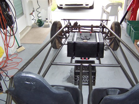
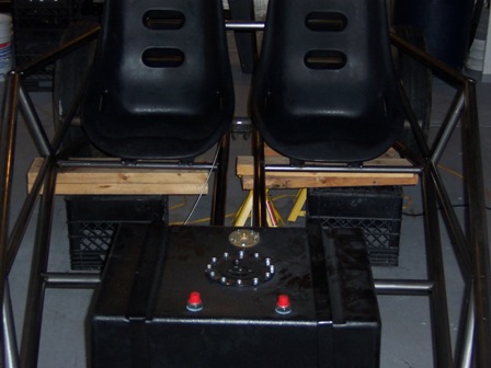
I got the fuel cell from Jegs. Its a 16 gallon cell with a fuel sump, sending gauge, mounting kit and vent. I'll cap one of the sump outlets and use it for a drain point if needed in the future and the other as the supply to the pump. It has a fuel return also for the fuel injection on the engine. I will mount an after market high pressure fuel pump and run #8 lines to and from the engine making it a safe setup in case of an accident.
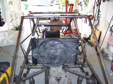
Better shot of the radiator mounting. Looks pretty ugly at this point, but after I set the engine in, it didn't look so big. It will be OK once its painted and dressed out. I can run the top left hose down and under the engine by the motor mounts to get to the water pump with a length of exhaust tubing sized correctly and with a couple of well placed bends. The upper right will be a straight shot from the top of the engine to the radiator. I'll tack weld a ring on each end of the tubing for both runs to give the radiator hoses something to grip to when installed as well as double clamps at all points.
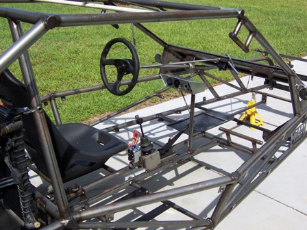
You can see all of the cockpit in this shot. Starting from the front edge of the seat, there is the turn signal box. I welded a short piece of 1.5" tubing to the back of the shifter box to mount this to. The shifting rod going back to the trans runs through this. Then the shifter and the e brake are in front of it. I mounted the e brake this way to be able to use the stock cables as well as ergonomics. It got real crowded in there. In front of the e brake, is the "instrument tower". I did it this way because with the windshield angle the way it is, there was no way to mount it under the windshield and be able to reach it even with the seat belts off. I didn't want it overhead as it is in the line of vision and there is no good way to run the wiring and make it look nice. Its within arms reach this way and the wiring is also more centralized and can be attached to the tubing and dressed out etc. Bottom right you can see the passenger foot rest I made matching the roll cage design.
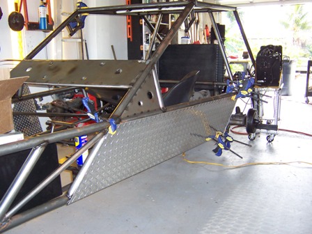
You can see the valence panels here again as well as the new 1/8" aluminum tread plates I made for the sides in this shot and the next. They will be painted a flat black on the inside of each of the four pieces.
I got these trick little side mirrors from Speedway. They have a lot of products for street rods, racing and muscle cars and you can find just about anything to make the project better looking as well as legal if you building for the street. That's all for now. I'll get more pics posted soon!
OK, on to page # 2. Click here!
|